
Calculating inverse kinematics for 6-axis robotic arms
A practical guide to math models and payload limitations when setting up reach and motion paths for industrial manufacturing cells.
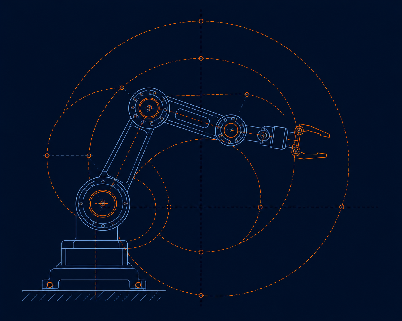
Inverse kinematics for 6-axis arms: a practical guide
Forward kinematics tells you where the end effector is, given joint angles — that's straightforward matrix chaining using Denavit-Hartenberg parameters. Inverse kinematics, going from a desired pose back to joint angles, is where most integration projects lose time, because a 6-axis arm typically has multiple valid joint solutions for the same pose.
Analytical vs numerical solutions
For arms with a spherical wrist (the last three axes intersecting at one point — true of most industrial 6-axis arms), the problem decouples: solve the first three joints for wrist position, then the last three for orientation, each in closed form. This is fast enough to run in a real-time control loop and is the standard approach for production cells.
Arms without a spherical wrist, or highly redundant arms with 7+ axes, generally need a numerical solver (Jacobian-based methods like damped least squares). These are more flexible but cost more CPU cycles per solve and can converge to local minima near singularities — budget extra margin in your cycle time if you go this route.
Handling multiple solutions
A 6-axis arm can typically reach a given pose in up to 8 distinct joint configurations (elbow up/down, wrist flipped, shoulder left/right). Picking the wrong one blindly can send a joint through a large, unnecessary motion or into a mechanical limit. The practical fix is scoring each candidate solution by total joint displacement from the current pose and picking the minimum — this keeps motion smooth and avoids surprising the operator.
Singularities are where the math and the mechanism disagree
Near a singularity (commonly: wrist axes aligning, or the arm fully extended), small Cartesian motions require disproportionately large joint velocities — the Jacobian becomes near-singular. Damped least-squares inversion trades a small amount of path accuracy for bounded joint velocities near these configurations, which is almost always the right trade in a production cell.
Payload and reach aren't independent numbers
A manufacturer's rated payload assumes the load is centered at the wrist flange with a specific center-of-gravity offset. Move the payload's center of mass further from the flange, or extend the arm near full reach, and the effective torque at the shoulder and elbow joints can exceed rated limits well before you hit the arm's stated payload figure. Always check the manufacturer's payload-vs-reach-vs-offset chart, not just the headline number.
Takeaway: closed-form IK for spherical-wrist arms is fast, reliable, and should be your default; reach for numerical solvers only when the mechanism genuinely requires it, and always plan motion with singularities and true payload limits in mind, not just the reach circle in the datasheet.