
Passing EMC: Practical shielding for radiated emissions
Understanding the difference between near-field and far-field emissions, and how to design metal enclosures that pass CE marking first time.
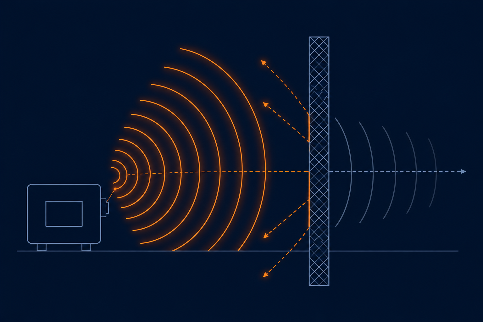
Passing EMC: practical shielding for radiated emissions
Radiated emissions are the test most hardware teams fear, largely because failures often trace back to layout decisions made months earlier that are expensive to fix at the enclosure stage. Understanding near-field vs far-field behavior early changes how you shield.
Near-field vs far-field, and why it matters for design choices
Within roughly one wavelength of the source (the near field), electric and magnetic field strengths behave independently and fall off quickly with distance — shielding close to the source is highly effective here. Beyond that distance (the far field, which is what CE/FCC radiated emissions testing actually measures, typically at 3 or 10 meters), the fields combine into a propagating wave that falls off much more slowly with distance. This is why a small local fix — a ferrite, a shielded cable — often has an outsized effect on far-field test results: you're suppressing the source before it ever couples into a radiating structure.
Where radiating structures actually come from
Cables are usually the real antennas, not the PCB itself. A switching regulator's noise couples onto an unshielded cable via common-mode current, and that cable — often 1–2 meters long — radiates far more efficiently than the small PCB trace that generated the noise. Common-mode chokes on cable exits, and ferrite beads at connector shells, address this directly.
Designing metal enclosures that pass on the first try
- Seam and gasket continuity matters more than plate thickness. A single unshielded seam or a poorly compressed gasket creates a slot that can dominate your entire emissions profile at a specific frequency, regardless of how well-shielded the rest of the enclosure is.
- Cable entry points need dedicated treatment — a shielded connector or a filtered feedthrough, not just a hole with a grommet. An unshielded cable penetration is effectively a hole in an otherwise good shield.
- Ventilation openings should use a honeycomb or mesh pattern sized well below the wavelength of your highest concerning frequency — a rule of thumb is keeping the largest opening dimension under 1/20th of that wavelength.
- Bond the enclosure to PCB ground at multiple points, not a single ground wire — a single-point bond behaves like an antenna feed at higher frequencies rather than a shield connection.
Pre-compliance testing saves the schedule
A near-field probe and a spectrum analyzer on the bench, used during bring-up rather than only at the accredited lab, catches most of these issues weeks earlier and at a fraction of the cost of a failed formal test.
Takeaway: most CE marking failures aren't solved in the enclosure — they're solved by suppressing common-mode noise at the source and treating every cable exit and enclosure seam as a potential radiator.